Hi,
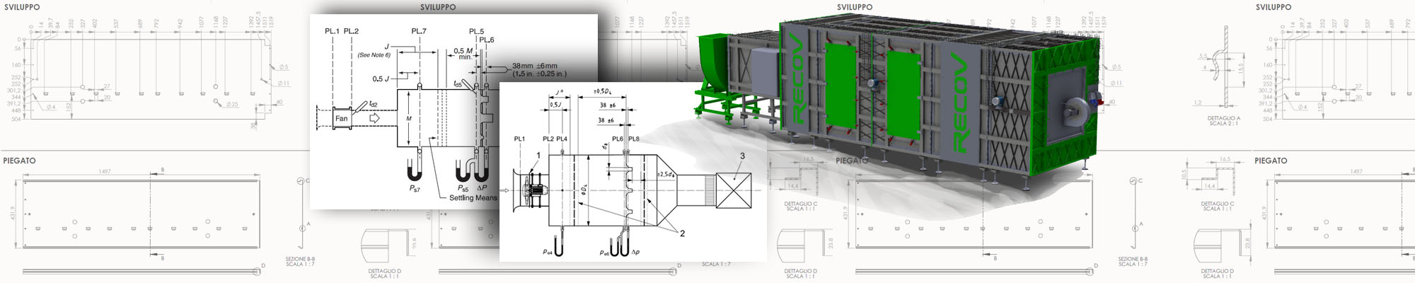
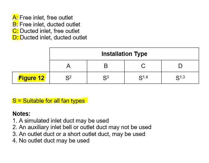
Figure 12 of the AMCA 210 - ANSI / ASHRAE 51 standard is one of the most popular setup in the world of fan testing. The AMCA 210 standard defines it as: Figure 12 - Outlet chamber setup - Multiple Nozzles In Chamber. A short description, but rich in content, which defines all its fundamental prerogatives.
Leaving aside the tube measuring systems, which I personally used at the beginning of my career and for which I do not have too much esteem, but maybe I'll talk about this later; Figure 12 is one of the most popular lay-outs being very effective and able to give satisfaction to anyone who approaches the aerodynamic performance measures of the fans.
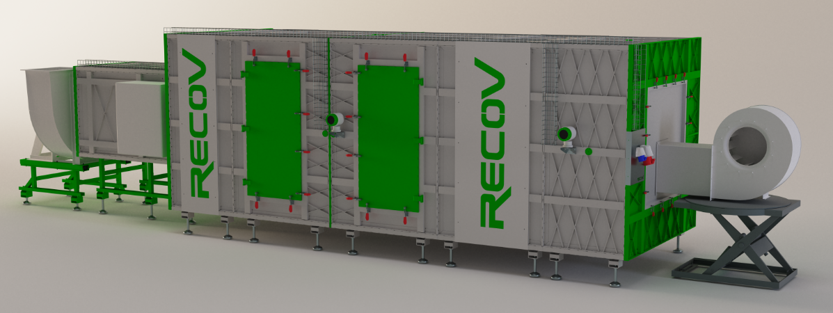
If well constructed, a fundamental premise, Figure 12 allows to obtain measurements of very high repeatability and very low uncertainty. No need for too complicated interpolations of the measurements that would add uncertainty to the measurement, in fact the layout provides for the measurement of the fan pressure (Ps7) near the outlet section of the fan under test, and the flow rate by measuring the pressure drop due to the calibrated nozzles.
In addition to its simplicity, Figure 12 has the following prerogatives:


RECOV S.R.L a socio unico - via A. Volta, 4 20834 Nova Milanese (MB) Italia - P.IVA 09003590966 - Cod. Dest. M5UXCR1